ISO 5211 defines the actuator mounting dimensions and drive square size.
Provided in the chart below is the ISO 5211 common dimensions and imperial/metric equivalents. You may also open/download and print-out the easy reference ISO 5211 pdf file.
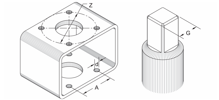
| MM INCH | A | Ød | ØZ | Number of Bolts | Bolt Ø | G |
|---|---|---|---|---|---|---|
| F03 | 25.4 1.00 | 5.5 7/32 | 36 1.417 | 4 | M5 10 – 24 | 9 .354 |
| F04 | 29.7 1.17 | 5.5 7/32 | 42 1.654 | 4 | M5 10 – 24 | 11 .433 |
| F05 | 35.4 1.39 | 6.5 5/16 | 50 1.969 | 4 | M6 1/4 – 20 | 14 .551 |
| F07 | 49.5 1.95 | 8.5 3/8 | 70 2.756 | 4 | M8 5/16 – 18 | 17 .669 |
| F10 | 72.1 2.84 | 10.5 7/16 | 102 4.016 | 4 | M10 3/8 – 16 | 22 .866 |
| F12 | 88.4 3.48 | 12.5 9/16 | 125 4.921 | 4 | M12 1/2 – 13 | 27 1.063 |
| F14 | 99 3.90 | 17 3/4 | 140 5.512 | 4 | M16 5/8 – 11 | 36 1.417 |
| F16 | 116.7 4.59 | 21 7/8 | 165 6.496 | 4 | M20 3/4 – 10 | 46 1.811 |
Dimensions in mm and in.
For the complete standard please visit www.iso.org/standard/62594.html.